EC2 §6.2: Complete Shear Design Worked Example (Free Download)
The Problem
A 6 m simply supported internal beam in an office building, at 5 m centres, carries g_k = 35 kN/m (slab, finishes, self-weight) and q_k = 20 kN/m (office + movable partitions). Concrete C30/37, steel B500B. A compact bending pre-step gives 4H25 as the main steel. The task: design the vertical links, and walk through every EC2 shear check — V_Rd,c, V_Rd,max, required A_sw/s, minimum reinforcement and spacing limits — with each intermediate value shown.
The Relevant Clauses
- §6.2.1(8): shear may be checked at distance d from the support face
- §6.2.2(1), Eq (6.2a/b): V_Rd,c for members without shear reinforcement
- §6.2.2(6), Eq (6.5)/(6.6N): cap on V_Ed, strength reduction factor ν
- §6.2.3(2)/(3), Eq (6.7N)/(6.8)/(6.9): truss model — V_Rd,s, V_Rd,max, θ limits
- §6.2.3(3), Eq (6.8): required link area for vertical links
- §9.2.2(5)–(8), Eq (9.4), (9.5N), (9.6N), (9.8N): minimum links and spacing limits
- Recommended values used throughout — check your National Annex
Input Data
| Parameter | Value | Unit | Notes |
|---|---|---|---|
| Span L | 6000 | mm | Simply supported |
| Tributary width | 5000 | mm | 5 m grid |
| b_w | 300 | mm | Beam width |
| h | 600 | mm | Overall depth |
| g_k | 35 | kN/m | Permanent, incl. self-weight |
| q_k | 20 | kN/m | Office + movable partitions |
| f_ck | 30 | MPa | C30/37 |
| f_yk | 500 | MPa | B500B |
| c_nom | 35 | mm | XC1, structural class S4 |
| Main bars | 4H25 | — | From bending pre-step (Step 3) |
| Links | H8, two legs | — | To be sized |
Step-by-Step Calculation
Step 1: Design Loads and Shear Force
Load combination per EN 1990 Eq (6.10), persistent design situation:
w_d = 1.35 × 35 + 1.5 × 20 = 77.25 kN/m
Shear at the support centreline: V = 77.25 × 6.0 / 2 = 231.8 kN.
Effective depth: d = 600 − 35 − 8 − 25/2 = 544.5 mm.
Because the beam carries a predominantly uniformly distributed load, §6.2.1(8) permits checking shear at distance d from the support face. With a 300 mm support width:
V_Ed = 231.8 − 77.25 × (0.150 + 0.5445) = 178.1 kN
If we skipped this rule and checked at the face (220 kN), we would be over-designing the links by about 25%. The reduction is a real clause, not a convenience.
Step 2: Material Properties
f_cd = 1.0 × 30 / 1.5 = 20.0 MPa (§3.1.6(1)P NOTE, α_cc = 1.0 — the recommended value and the French NA value; the UK NA adopts 0.85)
f_yd = f_ywd = 500 / 1.15 = 435 MPa (§3.2.7(2), §6.2.3(3))
f_ctm = 2.9 MPa (Table 3.1, C30/37)
Step 3: Effective Depth and Flexural Steel (Compact Pre-Step)
The V_Rd,c formula needs the longitudinal tension ratio ρ_l, so the bending design is a prerequisite. Here it is in compact form (it gets its own full post):
K = M_Ed / (b d² f_ck) = 347.6×10⁶ / (300 × 544.5² × 30) = 0.130 ≤ 0.167 — no compression steel needed
z = d × [0.5 + √(0.25 − K/1.134)] = 472 mm
A_s = M_Ed / (f_yd × z) = 347.6×10⁶ / (435 × 472) = 1692 mm² → provide 4H25 (1963 mm²)
Checks: A_s,min = 0.26 × 2.9 × 300 × 544.5 / 500 = 246 mm² ✓ (governs over the 0.0013·b·d = 212 mm² floor, §9.2.1.1(1)); A_s,max = 0.04 × 300 × 600 = 7200 mm² ✓ (§9.2.1.1(3))
ρ_l = 1963 / (300 × 544.5) = 1.20% ≤ 2% ✓
Step 4: Can the Concrete Work Alone? V_Rd,c
k = 1 + √(200/544.5) = 1.61 ≤ 2.0
V_Rd,c = [C_Rd,c × k × (100 × ρ_l × f_ck)^(1/3) + k₁ × σ_cp] × b_w × d (Eq 6.2a)
With C_Rd,c = 0.18/1.5 = 0.12, σ_cp = 0 (no axial force):
V_Rd,c = [0.12 × 1.61 × (100 × 0.0120 × 30)^(1/3)] × 300 × 544.5 = 104.0 kN
Minimum (Eq 6.2b, with v_min from Eq 6.3N): v_min = 0.035 × 1.61^1.5 × √30 = 0.390 MPa → 63.7 kN
V_Rd,c = 104.0 kN < V_Ed = 178.1 kN → shear links are required.
For completeness, the absolute cap on V_Ed from §6.2.2(6): 0.5 × b_w × d × ν × f_cd = 0.5 × 300 × 544.5 × 0.528 × 20.0 = 862 kN ✓
Step 5: Strut Check — V_Rd,max
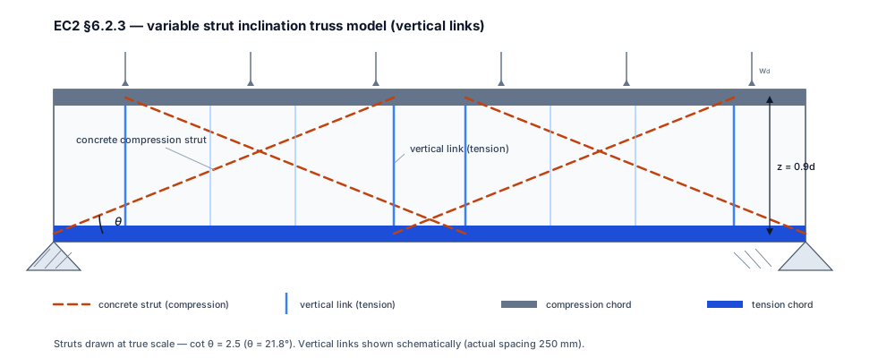
The truss model we are working with. Note the struts: cot θ = 2.5 means each one runs 2.5 times further horizontally than the lever arm z — genuinely flat, which is why the links do most of the work.
Strength reduction factor (Eq 6.6N): ν = 0.6 × (1 − 30/250) = 0.528
Here is a trap worth knowing: ν₁ may be taken as 0.6 for f_ck ≤ 60 MPa only when the design stress of the links is below 0.8 f_yk (Note 2 to §6.2.3(3)). With f_ywd = 435 MPa that condition does not hold, so we use ν₁ = ν = 0.528. Taking 0.6 would overestimate V_Rd,max by 14%.
z = 0.9d = 490 mm (§6.2.3(1))
Calculate the strut angle from the demand by setting V_Ed equal to V_Rd,max (Eq 6.9) — the angle at which the concrete strut would just reach capacity:
sin 2θ = 2 × V_Ed / (α_cw × b_w × z × ν₁ × f_cd) = 2 × 178.1×10³ / (1.0 × 300 × 490 × 0.528 × 20.0) = 0.229 → θ = 6.6°
That is below the lower limit of Eq 6.7N (21.8°), so the code minimum governs: θ = 21.8°, cot θ = 2.5. The demand angle being far below the limit shows the section is over-strength in shear; the code minimum, not the demand, fixes the angle.
V_Rd,max = α_cw × b_w × z × ν₁ × f_cd / (cot θ + tan θ) (Eq 6.9)
= 1.0 × 300 × 490 × 0.528 × 20.0 / (2.5 + 0.4) = 535.3 kN > 178.1 kN ✓ (ratio 0.33)
Even at θ = 45° the ceiling is 776.2 kN — the section is comfortably sized for shear. §6.2.1(8) also requires the shear at the support to be checked against the strut capacity: V = 231.8 kN < 535.3 kN ✓.
Step 6: Required Links
A_sw/s = V_Ed / (z × f_ywd × cot θ) (Eq 6.8, rearranged)
= 178.1×10³ / (490 × 435 × 2.5) = 0.334 mm²/mm = 334 mm²/m
H8 two-leg links: A_sw = 2 × 50.3 = 100.5 mm² → s = 100.5 / 0.334 = 301 mm.
Try H8@300: V_Rd,s = 100.5/300 × 490 × 435 × 2.5 = 178.5 kN (Eq 6.8) — passes at a ratio of 0.998.
Technically that works. I would never detail it that tight. Rounding to H8@250 gives V_Rd,s = 214.2 kN (ratio 0.83) for about 0.5 kg of extra steel per metre of beam. When the ratio on a hand calc is 0.998, the field tolerance of your bar bending has already eaten your margin.
Step 7: Minimum Links and Spacing Limits
Minimum: ρ_w,min = 0.08 × √f_ck / f_yk = 0.000876 (Eq 9.5N) → A_sw,min/s = 0.000876 × 300 = 263 mm²/m < 402 mm²/m provided ✓
Longitudinal spacing: s_l,max = 0.75 × d = 408 mm > 250 mm ✓ (Eq 9.6N, α = 90°)
Transverse spacing: s_t,max = 0.75 × d = 408 mm ≤ 600 mm ✓ (Eq 9.8N)
Not covered here, but required in the full design: anchorage of the bottom bars at the end support (§9.2.1.4). Treat this post as the shear slice of a complete beam design, not the whole job.
Result Summary
| Check | Required | Provided | Ratio | Pass? |
|---|---|---|---|---|
| V_Rd,s ≥ V_Ed (Eq 6.8) | 178.1 kN | 214.2 kN | 0.83 | ✅ |
| V_Rd,max ≥ V_Ed (Eq 6.9) | 178.1 kN | 535.3 kN | 0.33 | ✅ |
| V_support ≤ V_Rd,max (§6.2.1(8)) | 231.8 kN | 535.3 kN | 0.43 | ✅ |
| A_sw/s (Eq 6.8) | 334 mm²/m | 402 mm²/m | 0.83 | ✅ |
| A_sw,min/s (Eq 9.5N) | 263 mm²/m | 402 mm²/m | 0.65 | ✅ |
| s ≤ s_l,max (Eq 9.6N) | 408 mm | 250 mm | 0.61 | ✅ |
Design: H8 links at 250 mm centres, two legs.
Download
📥 Download the full calculation spreadsheet
Four sheets: Inputs, Steps (every formula with its clause), Summary, and Notes. The file regenerates from a Python script, so the numbers in this post and the spreadsheet cannot drift apart. Fully free — no gate, no signup.
If you spot a mistake or want a variation of this example, write to me at hugo@civion.cloud — corrections to published calculations go straight to the top of my list.
What I’m Building
I’m building a tool that runs this exact sequence — section in, it checks V_Rd,c, V_Rd,max, sizes the links, and flags the traps before you hit them: the ν₁ shortcut, the NA differences, the 0.998 near-miss. Twenty minutes of arithmetic becomes twenty seconds. If that sounds useful, write to me at hugo@civion.cloud and I’ll tell you when it’s ready.
Verified against EN 1992-1-1 §6.2 by the author.